 English
 中文简体
中文简体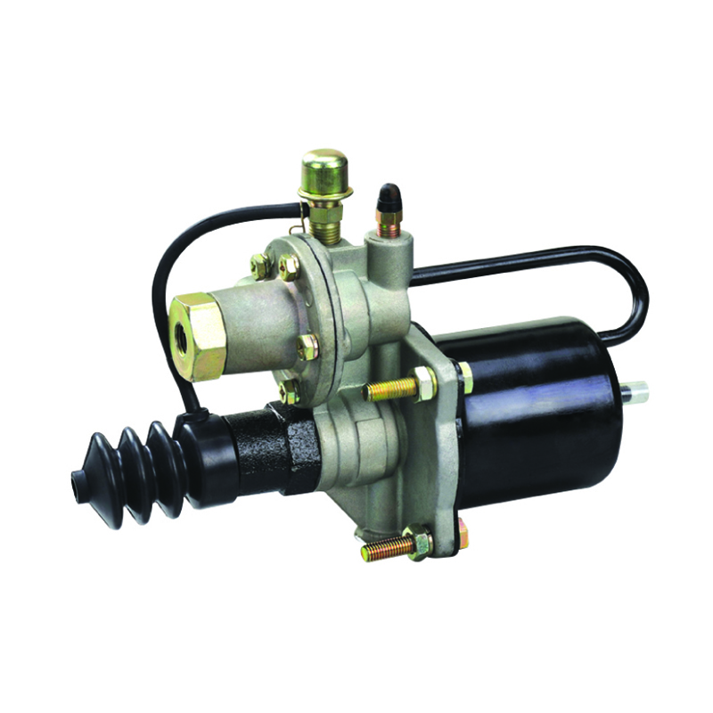
For exclusive deals and latest offers, signup by entering your email address below.
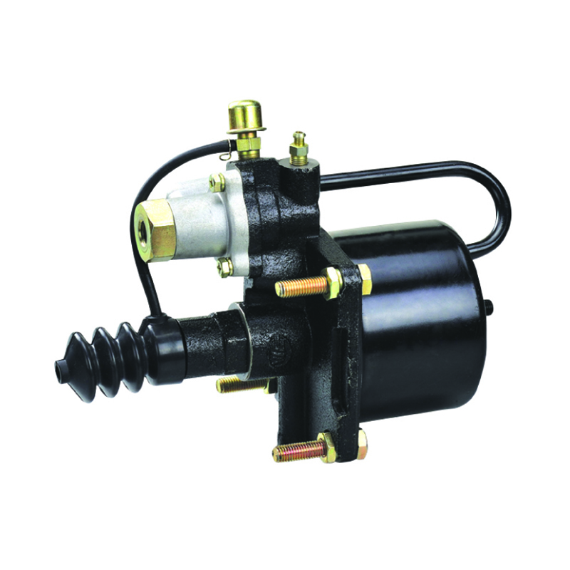
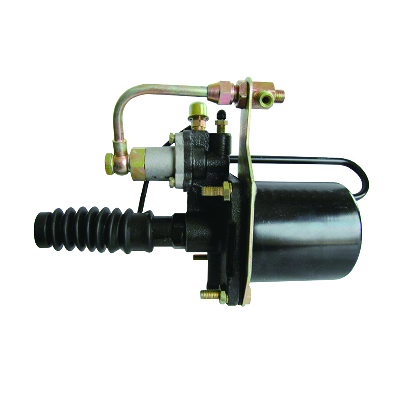
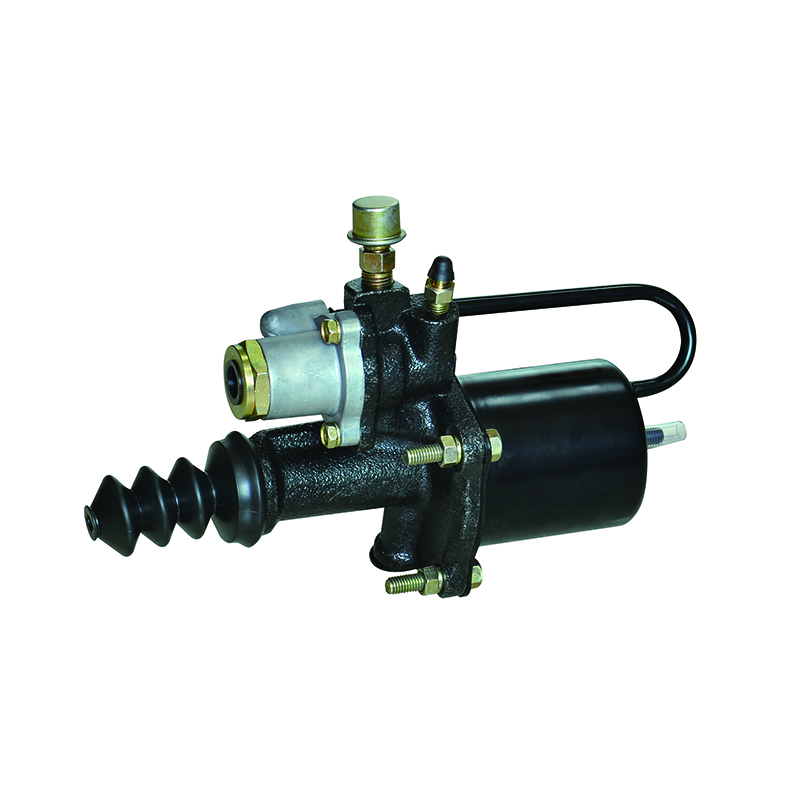
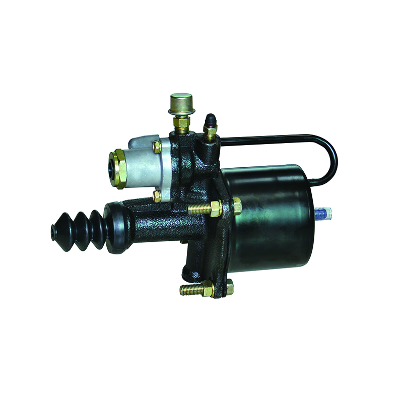
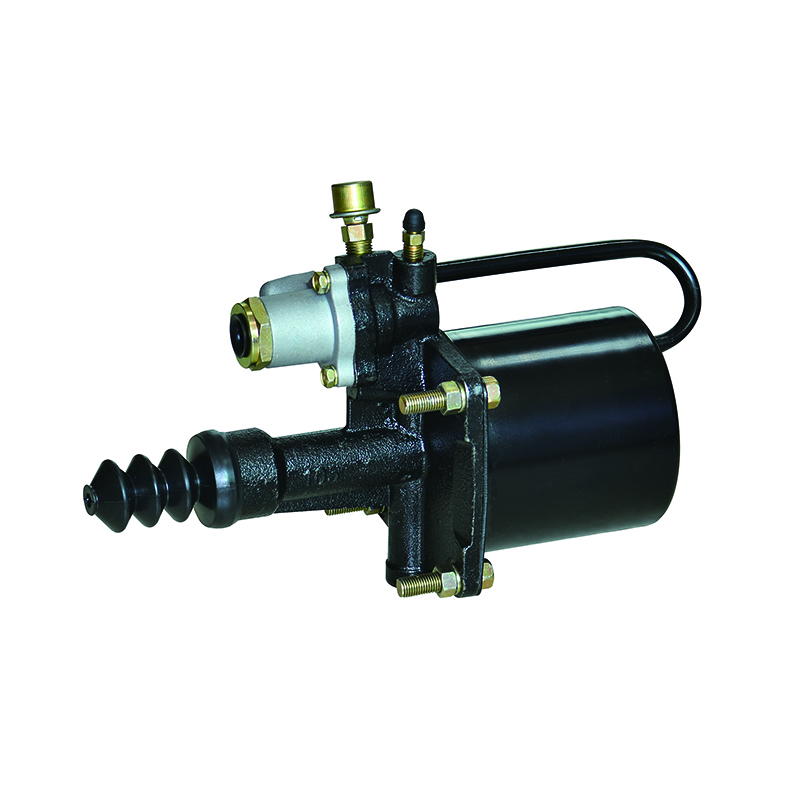
Clutch Booster Assembly of the Present Invention
A clutch booster is an important component of the clutch system. It has been used in vehicles such as heavy trucks, light trucks, engineering machines, and coaches. Clutch boosters help reduce pressure needed by the clutch pedal and extend the operating time of the clutch. But in order to use a clutch booster properly, you need to ensure that the device is maintained and serviced.
The main part of a clutch booster assembly is a hydraulic cylinder. In a conventional clutch booster, a master cylinder is connected to a clutch pedal. Pressurized brake fluid from the master cylinder transfers to the hydraulic cylinder of the clutch booster. This is then used to actuate the clutch. When the clutch pedal is released, the pressure in the cylinder is discharged.
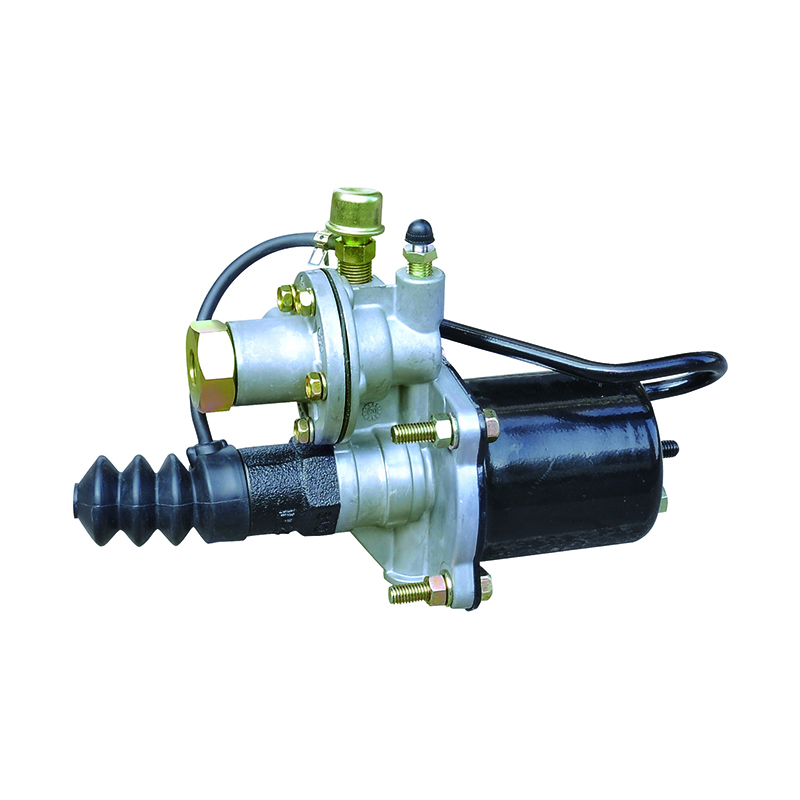
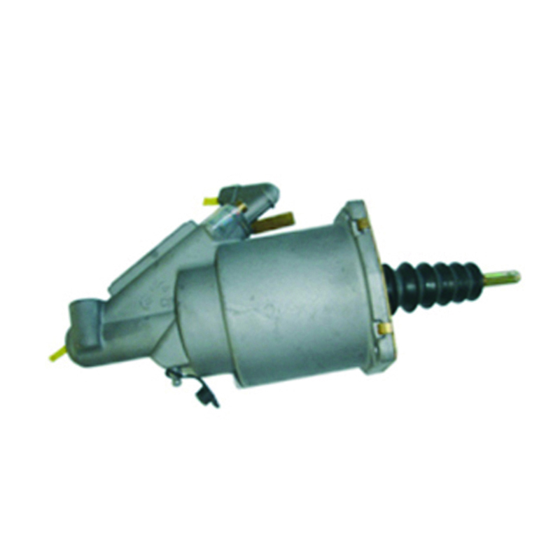
The vehicle clutch booster is a relatively simple structure. It prevents the entry of dust and rainwater, and its sealing performance is good. However, it is prone to malfunction. If the clutch booster is damaged, it may result in pedal sinking.
Besides reducing the amount of pressure required by the clutch pedal, the vehicle clutch booster also prevents the entrance of dust and impurities into the system. Moreover, it has long life, stable use performance, and good sealing.
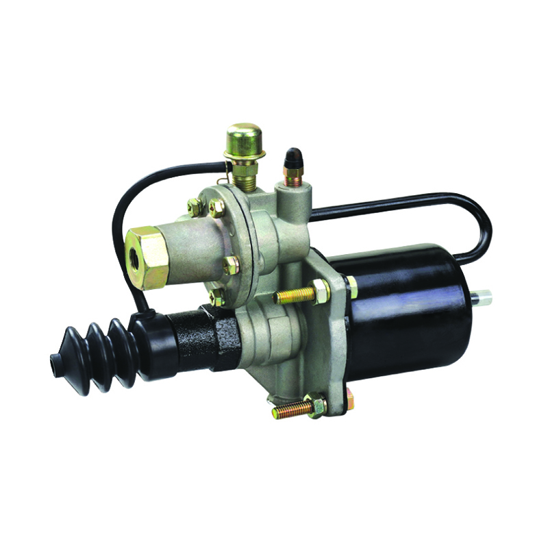
Boosters of the present invention are provided with a piston mounted in a housing. In addition, the boosting piston is able to judge the status of the clutch. For instance, the piston can be used to assess the reunion and separation states of the clutch. Another aspect of the clutch booster is that it is capable of preventing the leakage of hydraulic fluid. As a result, the clutch booster is efficient and can be used without requiring continuous pump flow.
Among the above mentioned features, a novel feature is the capability of the clutch booster to prevent fluid leakage. An annular chamber is formed between the piston and the housing. Alternatively, the second annular chamber can be selectively pressurized.
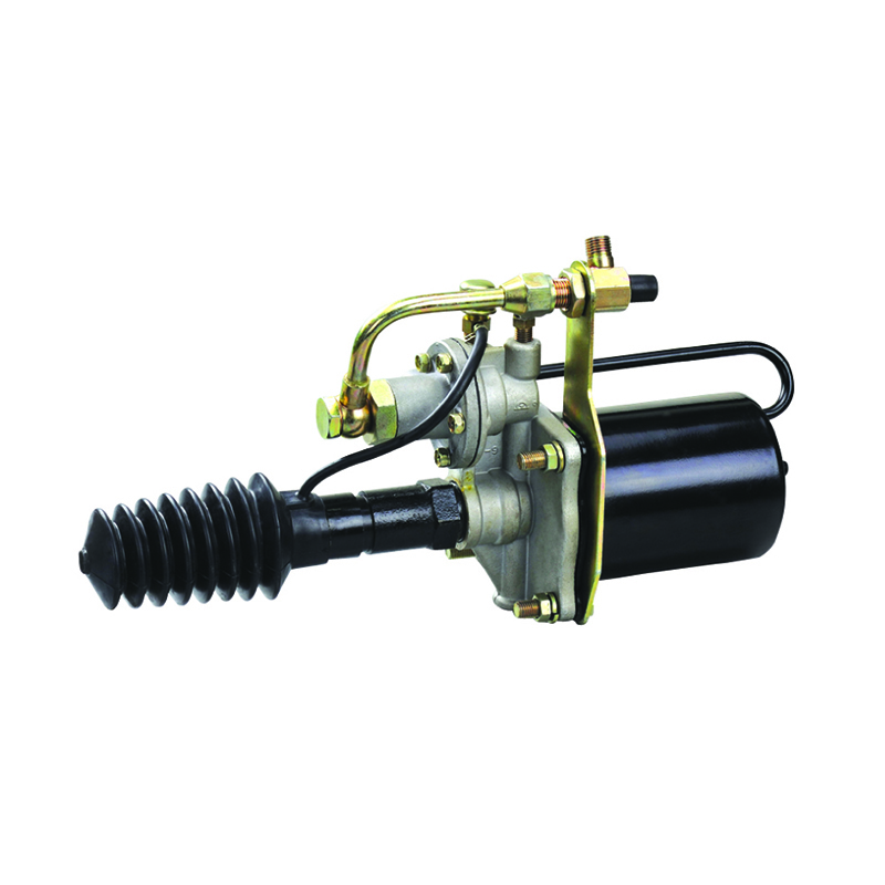
Furthermore, the relay piston is subject to air and hydraulic pressure. Its surface area is based on the ratio between the air pressure and the hydraulic pressure. Typically, the ratio is 0.495 or 0.5. This allows the balancing of the relay piston in response to changes in hydraulic pressure.
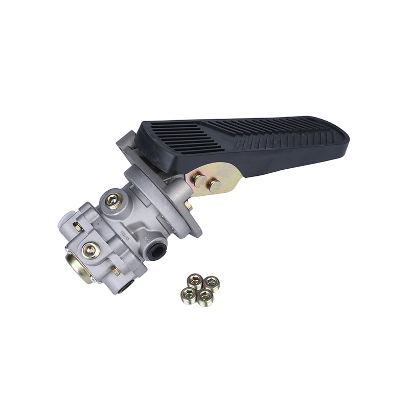
The boosting piston of the present invention includes an angular displacement sensor and a clutch friction plate abrasion alarm device. In addition, it is adapted to be mechanically linked to the pedal linkage. By displacing in a different direction than the booster piston, it is possible to determine the separation and reunion state of the clutch.
The input means is a reciprocal rod 27. The boosting piston moves the spacing post (16) in a limit in accordance with the movement of the hydraulic piston.
In order to maintain the output force of the clutch booster, the relay piston is also balanced with the hydraulic and air pressures. For example, the surface area of the relay piston is 2.02 square centimeters when the clutch is under hydraulic pressure.
Copyright© 2021 Zhejiang Great Science & Technology Co., Ltd. All Rights Reserved.
Truck Air Brake System Parts Manufacturers
